|
There are currently no product reviews.
 ;
perfect! you just sent to me the copy in Italian witout even my specification!!!! so you are really smart cooperative and efficient. To my opinion the best place all over to get a manual of electronics!!!!
;
Well Well Well!!!! Good manual perfect for my hobby!!! As Before you have done a very well done work!!!! Thank you
;
Super nice! Good to have a manual in digital format.
;
Great job supplying the manual.
Many of these products weerepretty obscure, so it was great that you had
the manual for it!
;
Great manual, would not have been able to operate my machine without it!!
James Dawson August 18, 2012
Model 204B
Section V Paragraphs 5-10 to 5-15
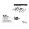
Figure 5-3. Cover Removal
5-10. REPAIR.
e. Remove bottom cover screw and lift tilt stand.
f . Slide bottom cover t o r e a r and lift t o remove.
5-11. When repairing the Model 204B, use the exploded view, figure5-4, as an aid t o identifying p a r t s . 5-12. COVER REMOVAL. 5-13. Remove covers prior t o any check or adjustment which requires power t o be applied. Refer t o figure 5-3, and proceed as follows:
g. Remove side cover screws and side covers. h. To replace covers and foot assembly, reverse the order of steps a through g.
5-14. SERVICING ETCHED CIRCUIT BOARDS. 5-15. The etched circuit boards used in the Model 204B require that the soldering iron tip be applied to the conductor side of the board when servicing. For large components, such as potentiometers, rotate the soldering iron tip from lead to lead while applying p r e s s u r e to the part to lift it from the board o r use a soldering tip such as Ungar #855 3/4 in. Cup Tip. In addition to the above information, the following should be observed. 5-3
a. Remove top cover screw.
b . Slide top cover t o r e a r , and lift t o remove. c. Slide r e a r foot assembly toward side while pushing foot release. d. Lift foot assembly to remove.
01369-2
|